Residual Stress Gradient Visualization
All code, images, and results are copyright protected ©
by
Ronald D. Kriz, Assoicate Professor
Department of Engineering Science and Mechanics, and
Director of the University Visualization and Animation Group
and
Mecit Yaman, Ph.D Graduate Candidate
(Advisor: Professor M. Harting)
Department of Physics
University of Cape Town, South Africa
Residual stresses are present in most materials as a result of
thermal and mechanical loads applied during fabrication. For
example metals are "forged" into a desired shape with large loads
at high temperatures. But when the fabrication loads are removed
and the outside surface is cooled faster at the surface, larger
thermal contractions occur at the surface compared to the
interior. Micro-structures are also different at the surface
and upon further cooling stresses are frozen even after loads
are removed. Hence the name residual stress. A similar process
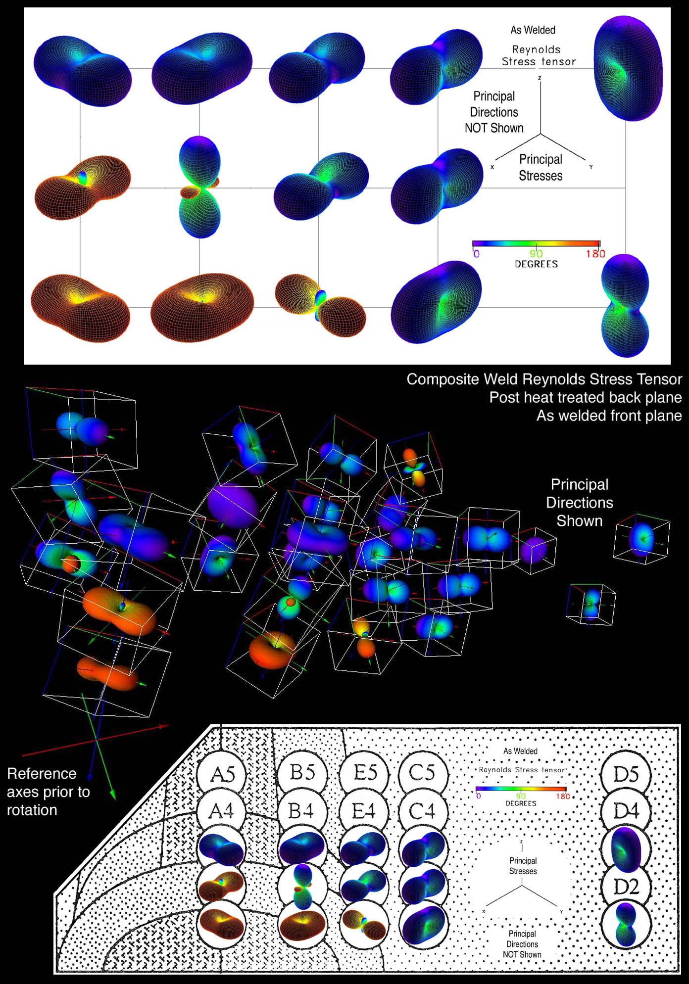
occurs in the formation of welds. Often these stresses are
unknown but sufficiently large such that cracks initiate and grow
causing unexpected failure. It is common practice to remove these
"as-welded" residual stresses by "post heat treatment". In some
cases residual stress can be controlled for a desired beneficial
result, e.g. residual stresses are intentionally created in
tempered glass where compressive stresses are created near the
surface that prevents crack growth and raises the fracture
strength. Residual stresses are associated with space gradients,
e.g. again in tempered glass compressive stresses near the
surface change to tension below the surface. Residual stress
gradients are important in understanding and predicting matertial
response.
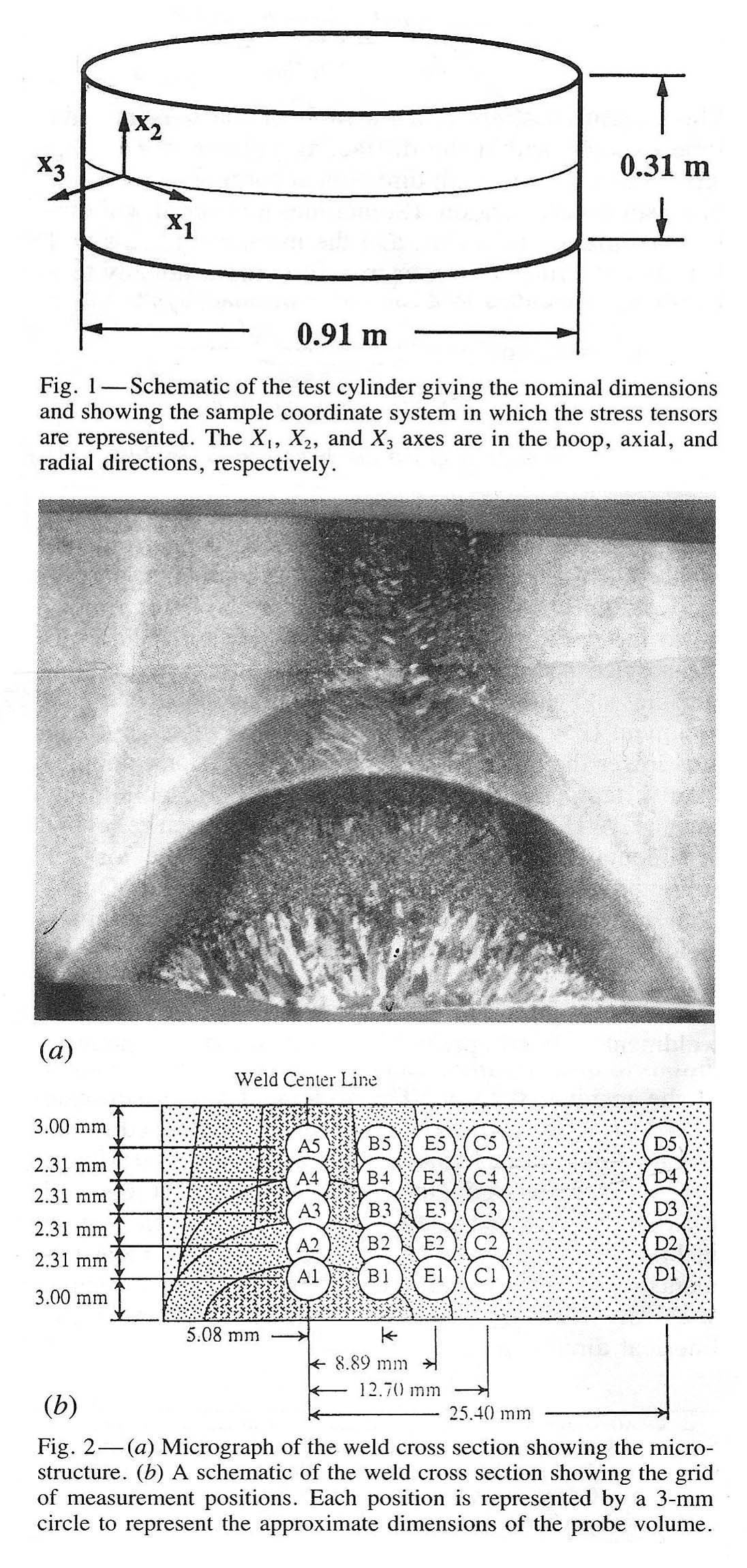
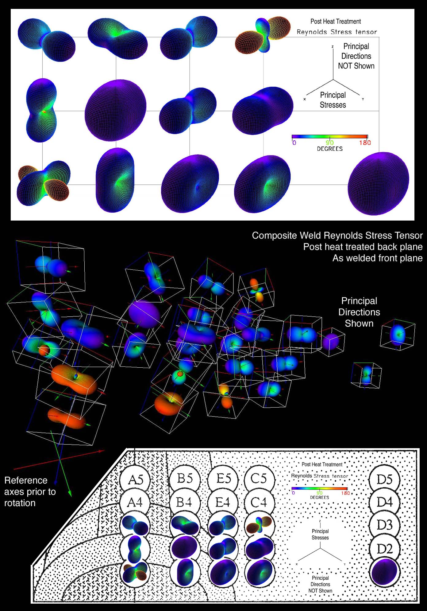
Below we study two different types of stress gradients in metals:
1) residual stresses near welds, Winholtz & Krawitz [1] and 2)
surface residual stresses induced by plastic deformations (shot
peening) in a Titanium alloy (Ti-6Al-4V), Harting [2]. In both
cases second order tensor glyphs are used to assist in
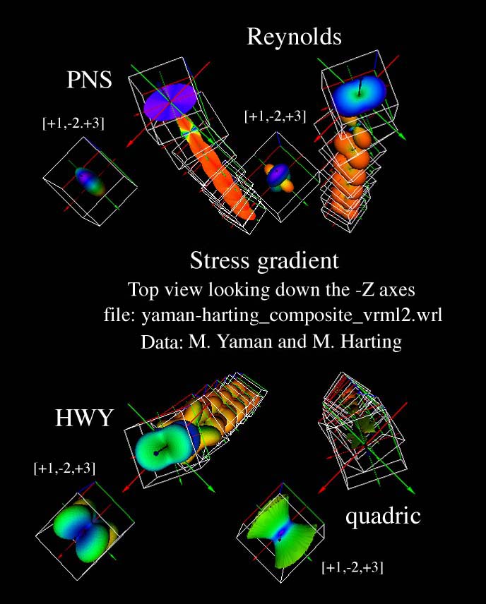
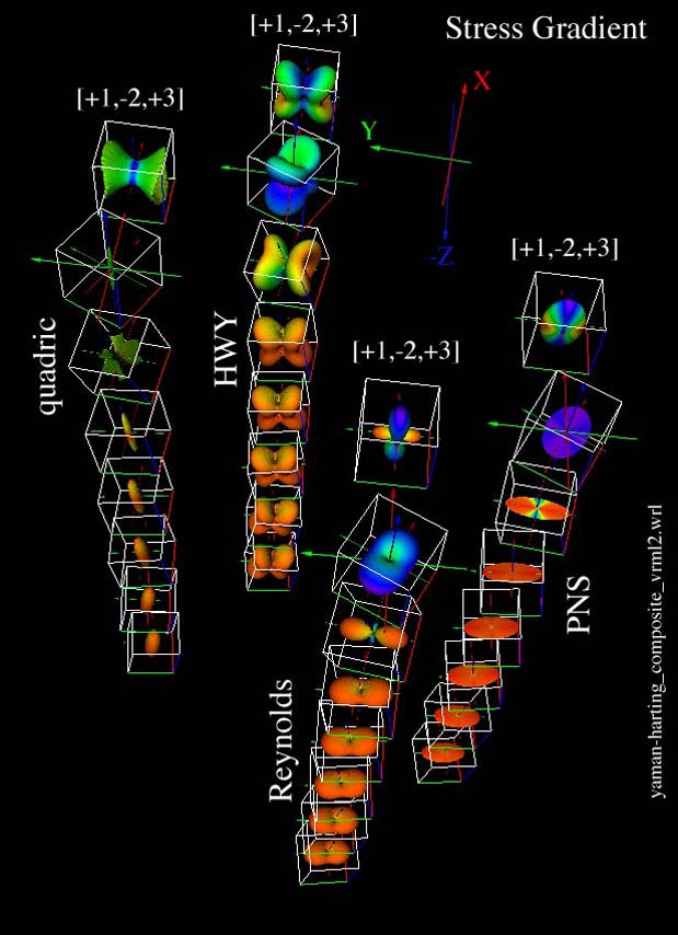
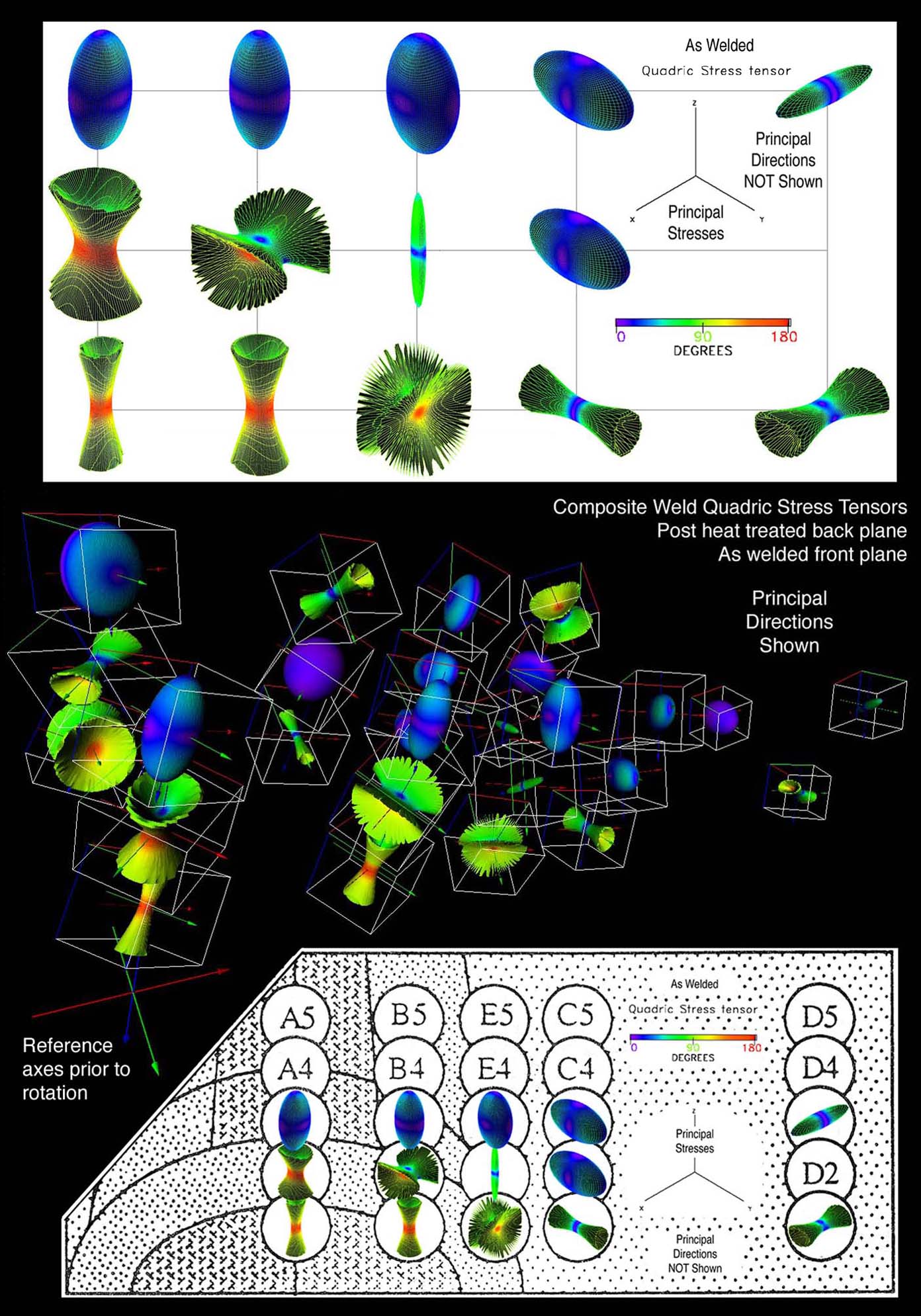
understanding the stress distribution ("gradient"). For comparison
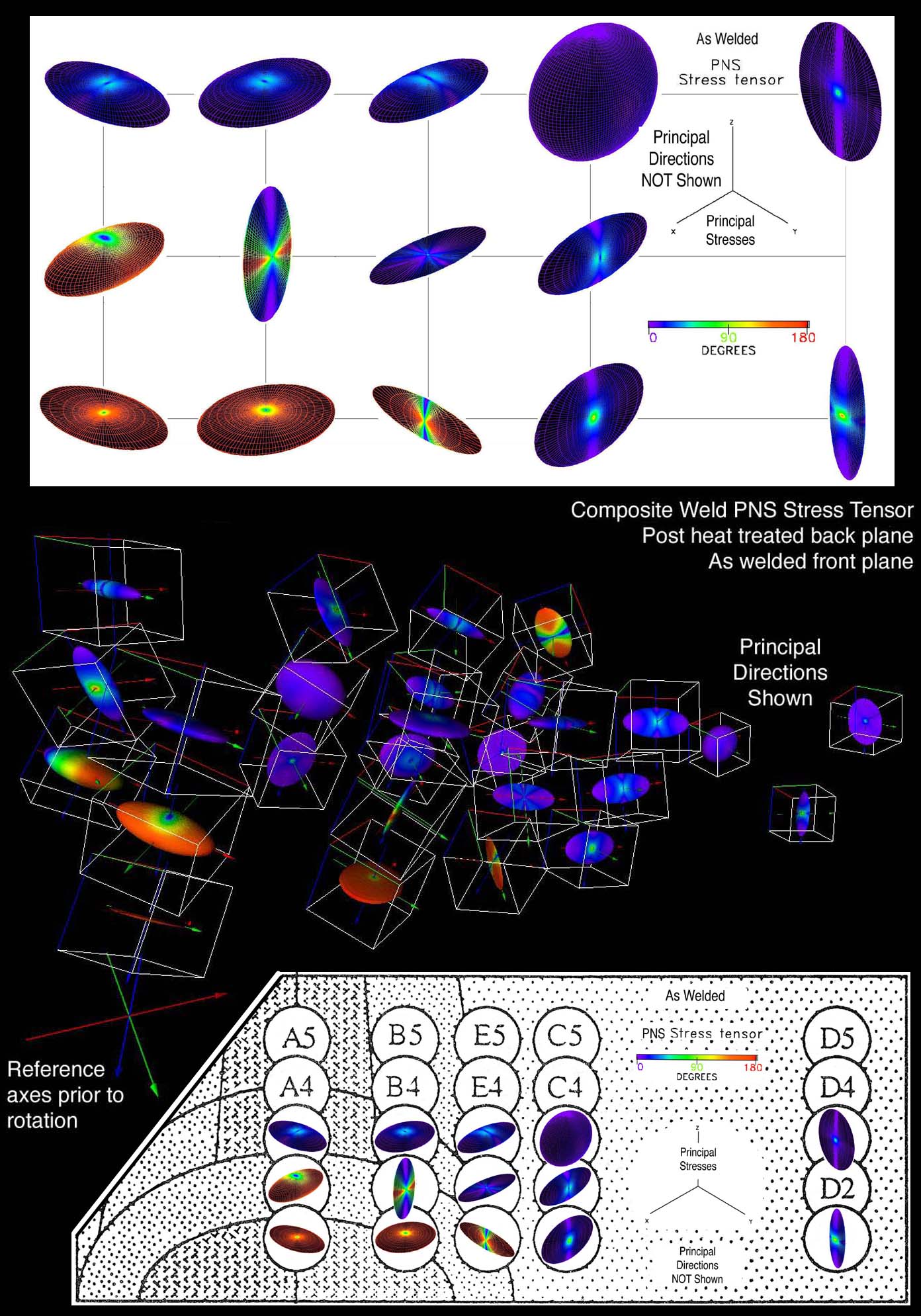
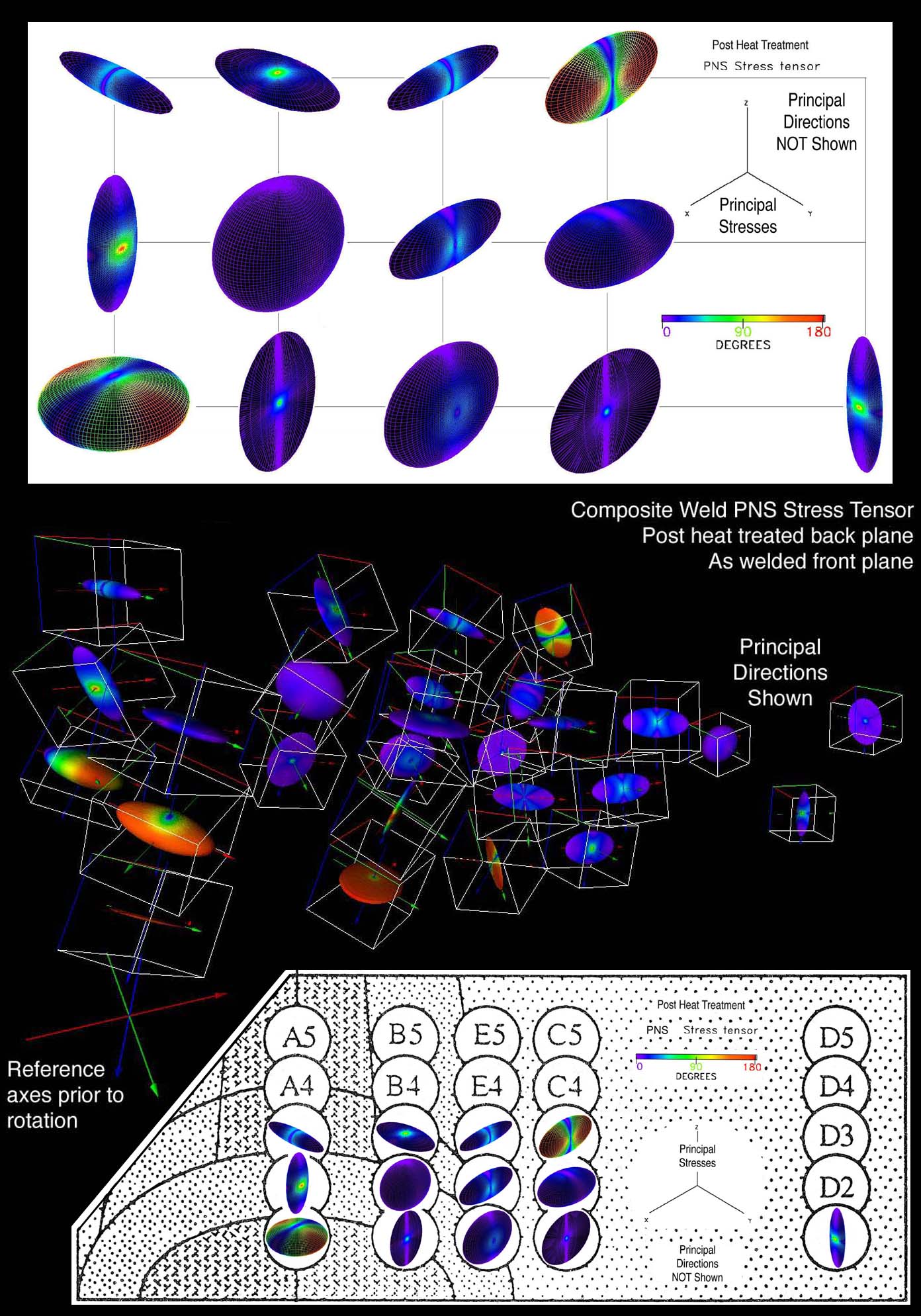
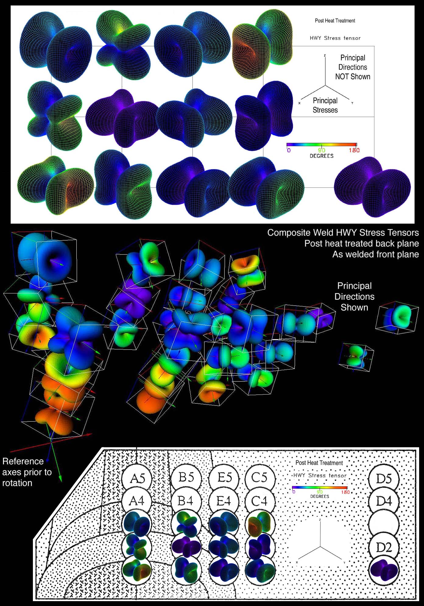
four different types of stress tensor glyphs are used: 1) Quadric,
Frederick & Chang [3], 2) Reynolds, Moore & Schorn [4], 3) HWY,
Hashash, Yao, and Wotring [5], 3) PNS, Yaman, Kriz, and Harting
[6]. The Quadric, HWY, and PNS glyphs' shapes emphasize the shear
component of the stress tensor, whereas the Reynolds glyph
shapes emphasize the normal component of the stress tensor. For
all glyphs a color gradient is superposed onto the glyph surface
that represents pure tension with purple (0-degree), pure shear
with green (90-degree), and pure compressive with red (180-degree).
Not previously known was that the Quadric glyph does not always
yield an ellipsoid but when shear exists cones appear instead. As
expected in all cases green appears on the conical part of the
quadric glyph. Each glyph type has its advantages and
disadvantages which are selected depending on the knowledge and
intent of the researcher. Hence scientific data visualization is
a creative process that is best realized by the applied scientist.
As educators our goal is to encourage the next generation of
applied scientists and engineers to become as skillful and
creative with computer graphical modelling as we are currently
skillful at mathematical modeling. Both will prove to be
essential for problem solving in the future.
References:
- R.A. Winholtz and A.D. Krawitz, Methods for depth profiling complete stress tensors using
neutron diffraction, Advances in X-Ray analysis, Vol. 37, Plenum Press, New York, 1994.
- M. Harting, "A seminumerical method to determine the depth profile of the three dimensional
residual stress state with x-ray diffraction", Acta Mater, Elsevier Science, Vol.
46, no. 4, pp. 1427-1436,1998.
- D. Frederick and T.S. Chang, Continuum Mechanics, Scientific Publishers, Inc. Boston, pp.
38-40, 1972.
- Y.M.A. Hashash, J.I. Yao, and D.C. Worting, "Glyph and hyperstreamline representation of
stress and starin tensors and material constitutive response," Int. J. Numer. and Anal.
Meth. in Geomech., Vol. 27, pp. 603-626, 2003.
- J.G. Moore, S.A. Schorn, and J. Moore, "Methods of classical mechanics applied to
Turbulence Stresses in a Tip Leakage Vortex. Conference Proceedings of the ASME Gas
Turbine, Houston, Texas October 1994, (also Turbomachinery Research Group Report No.
JM/94-90).
- M. Yaman, R.D. Kriz, and M. Harting, "Stress Tensor Visualization With Applications To
Materials Research," submitted for review, 2005.